The fable of d
A weird story...
The Model 'D' was designed when I was about 3/4 of the way through constructing
the Model 'C2'. I realized at this point that I may have overbuilt the device and
was quickly getting away from what I had set out in the experiment. But being just
about done, I let myself finish the C2 just to see what would happen. If you haven't
read the C2 story, read it here
The Model 'D' was finished August 1999 after much research into the possibilities
of a different type of transmitting waves and media. This device was the first to
test the notion of the Archimedes wave continuing where I left off with the Model
'C' which strived to differ itself from a Marconi wave more commonly seen in today's
wireless information transmission systems. The notion was that such a wave could
transmit a exponentially greater amount of power while reducing the required input
to transmit the wave through the air. The Model 'D' was triggered with a pulse wave
of 5V p-p, a frequency of 139kHz, with a pulse delay of 1us. The Model 'D' used
the earth as a reference and its transmission pulse frequency was based on the oscillation
pattern of the earth's electrical currents for maximum efficiency. Here are some
pictures of the device:
A pulse generator is plugged at "input"; the outputs were used by the
SC-3 Parabolic Dish for transmission of the waveforms.
The two toggle switches are manual calibrations of the output form. The one on the
side [NORMAL / SIGNAL PRIME] is used to charge the internal coil.
A 3V battery is used to prime the coil via the switch. This model uses the
principle of letting the electrons in the subsequent transmission collect in one
end of the coil before subjecting it to pulse forms. This way, the total property
of the form is stored between the inductor (red) and the capacitor (blue) and tuned
by a variable capacitor just above the coil.
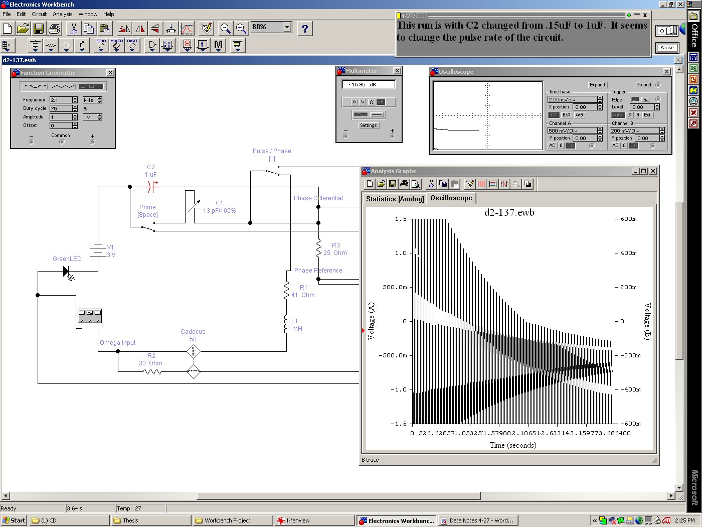
I tested the schematic in Electronics Workbench v5.12 in 2003. The output forms
looked as follows:
 >
>
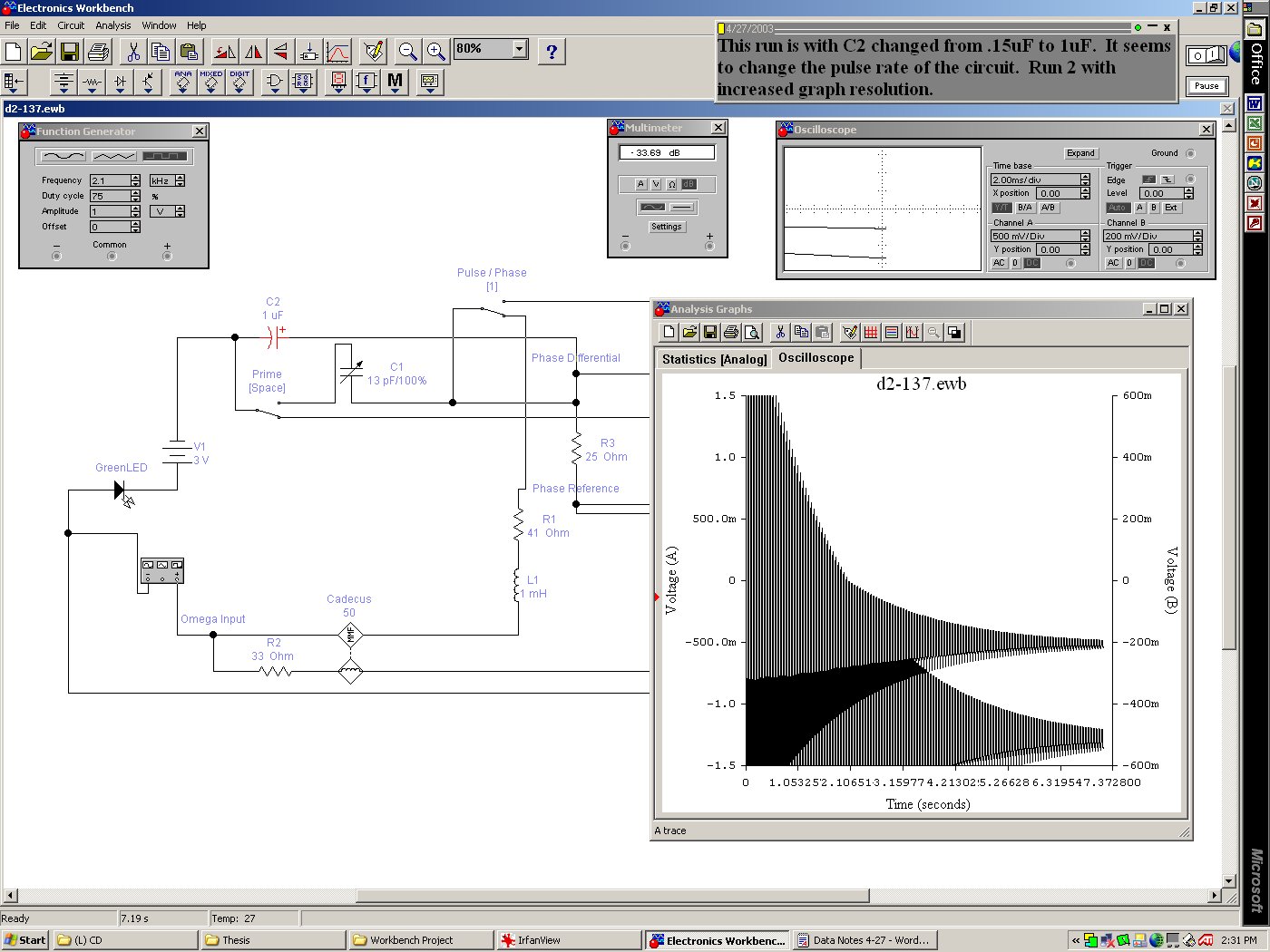
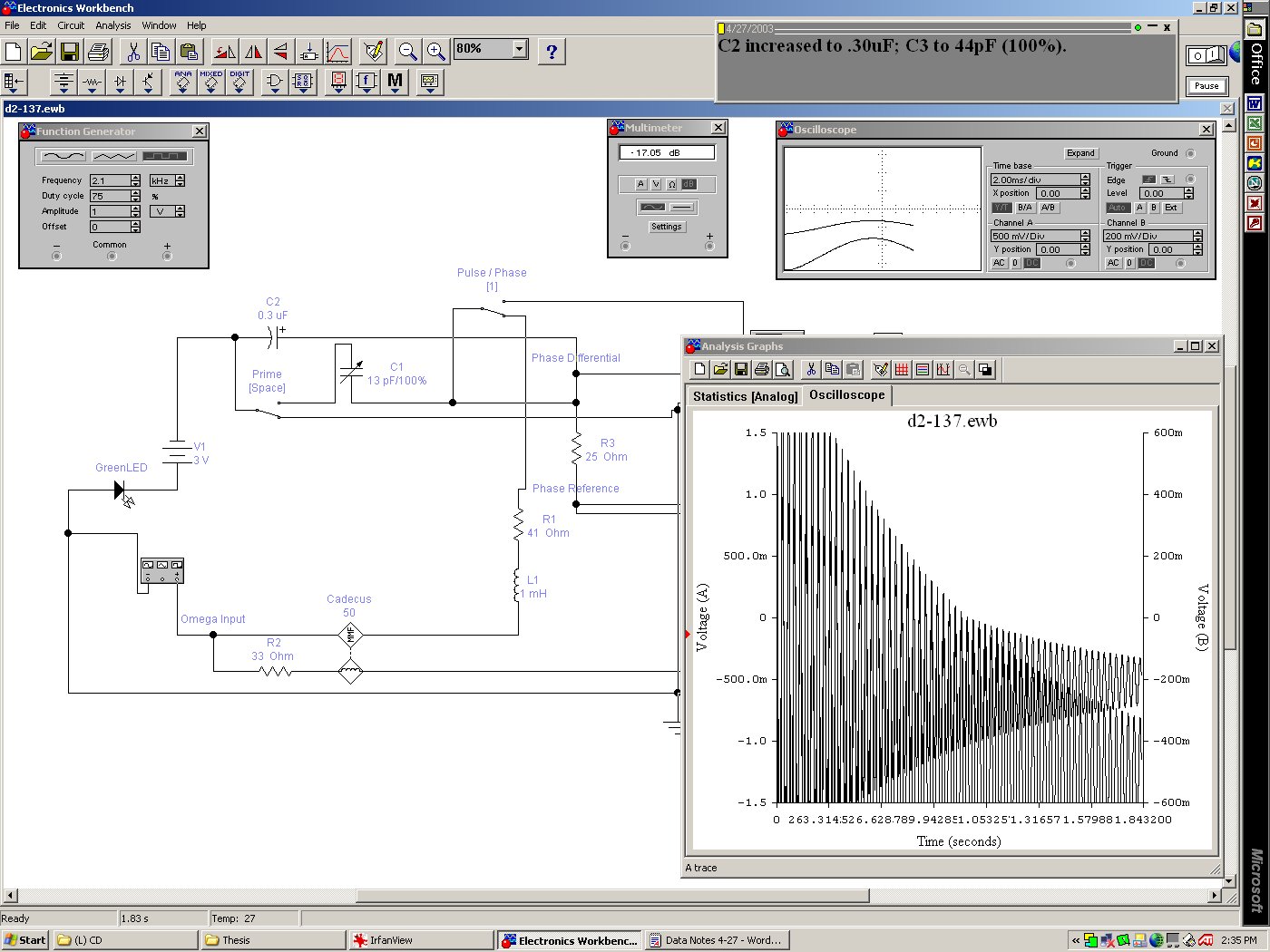
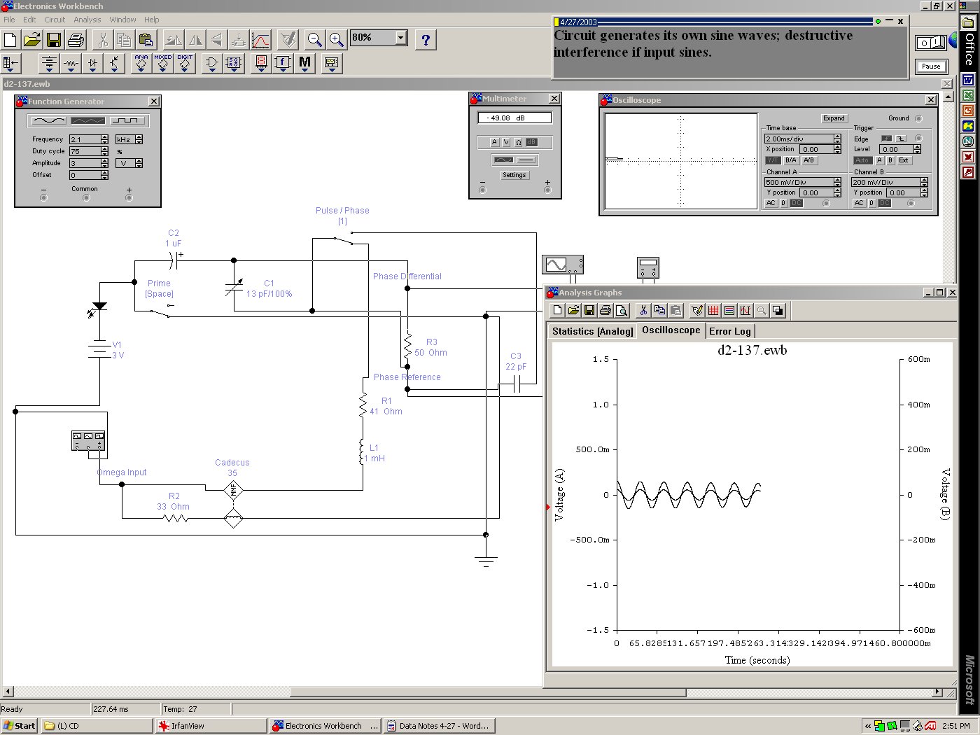
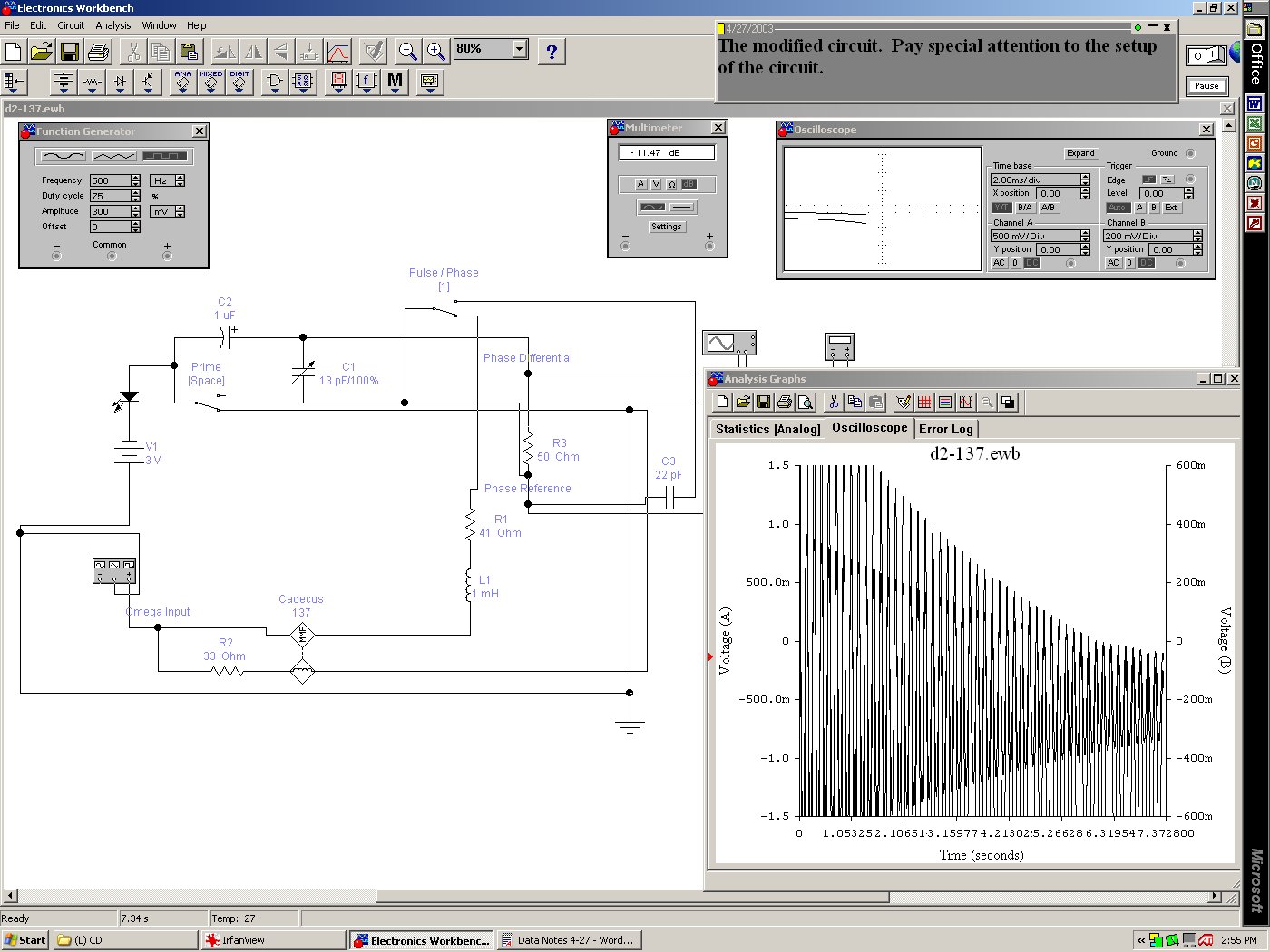
The five figures show tests conducted. Pay special attention to the interference
pattern in the "Analysis Graphs" window in the five figures. You can see
the equation (the operand or governing ODE) of the device being solved. This solution
pattern allows for the appearance of anti-electrons within the transmission stream;
the subsequent series progression indicates the type of wave transmitted--a spherical
wave. This was the first positive evidence that what I had designed the machine
to do was actually being accomplished. After these experiments, I returned to designing
the Model 'F'.
You can download the D2-137 schematic here.